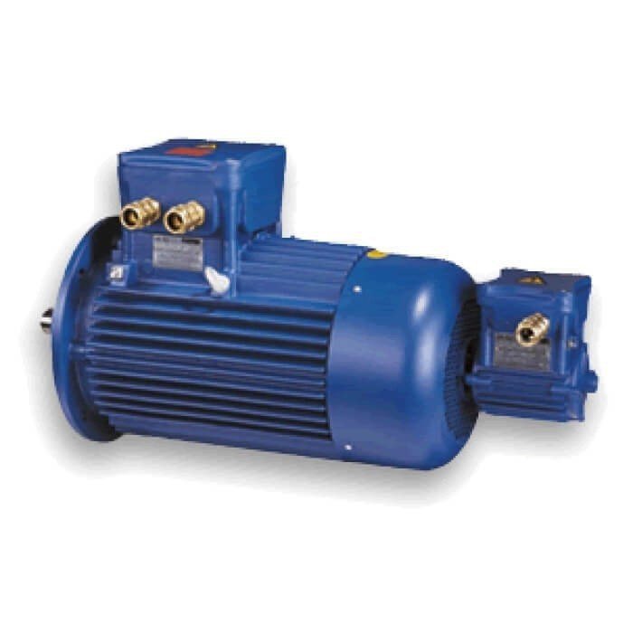
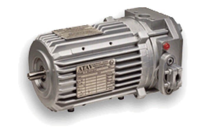
Series F aluminium/Inverter
- IEC 60079-0, IEC 60079-1, IEC 60079-7
- Ex-d, Ex-de
- Frame size 56 ÷ 80
- ATEX category 2D, 2G, 2GD
- Group IIB, IIC
- Temperature class T4, T5, T6
- To Norms IEC 61241-0, IEC 61241-1
- A21 - tD
- Protection IP55, IP65
- Maximum surface temperature [°C] T125, T85, T70
- To Norms IEC 60034-1,5,6,7,8,9,12,14, IEC 60072
- Power 0.06 ÷ 1.5 kW
- Three-phase 1 or 2 speed
- Single-phase
- Self cooled (IC411); forced cooling (IC416); unventilated (IC418)
- PAD mounting
Series F series Aluminum
- General information
The ATEX directive states that two diffrerent certificates of conformity are to be issued.
One is the “EC Standart Type” for the homologation of the prototype and the other is for the “Production Quality Assurance”.
The certificates are issued by the Laboratoire Central des Industries Electriques (L.C.I.E)
The production quality Guarantee certificate number is: LCIE 00 ATEX Q8007.
- Main characteristics
- Explosion-proof motors according to European standart CENELEC EN 50 014, EN 50 018 and EN 50 019 (for terminal box EEx-e)
- The European Standards are known and accepted by most Countries world-wide besides CENELEC (European Committee for Electrotechnical Standardization) member countries.
- Three phase and single phase Squirrel Cage Asynchronous Induction motors.
- Totally enclosed, fan cooled, frame IP55 with Terminal box IP65.
- The motors dimensions comply with IEC 60072 standard.
- Power supply 400V/50Hz.
Three-phase, 1-speed motors, 2-4-6-8 poles, T4, for sizes between 56 and 80, multi-voltage power supply 380-400-420 V/50Hz.
- Class F insulation.
- Noise level (dbA): Noise values measured both loadless and at the rated power supply condition are lower than those set forth by the NF 51-119 Standard (IEC 34-9). We can also provide special applications.
- Terminal box;
- Available both in a flameproof version or in an increased safety version
- Large size
- Normally installed on the side opposite the feet, can be oriented right – or leftwards frame separation grid.
- Rotating by 90 ° in 4 positions
- Frame separation grid.
- Motor frame
- Cooling fins
- Removable feet
- Pad for direct frame connection
- Removable through hole flange
- Front and back lip seal (IP55)
- Earthing screw.
- Rotor;
- In pressure cast aluminium alloy
- Shaft mounting by ring nut
- Dynamic balanced with feather key fully seated
- Insulating paint.
- High protection against corrosion:
- Stainless steel nameplate
- Anticorrosion plated fasteners.
- The following parts are highly resistant to impact:
- Cast aluminium fan cover.
- Low friction dust seals.
- Vibration level ;
The dynamic balacing of the rotors (half spline) allows for a level of residual vibrations in three-phase motors which correponds to the N degree according to IEC 34-14
- The conformity certificates also cover design characteristics that differ from the basci version, such as;
- Modification of the maximum installation altitude
- Modification of the rated voltage and rated frequency
- Power supply from an inverter
- Motor protection through temperature detectors
- Application for operation modes S2 to S9
- Main options
- Non-standard voltages and frequencies (maximum voltages 690 V)
- Motors with speacial electrical design.
- Motors suitable for frequency inverter drive.
- Special flanges and shafts.
- Double ended shafts.
- Grade R and S balancing
- Large motors with speacial bearing (unidirectional)
- Motors protection IP56-IP65-IP66.
- Tropicalised motors (relative humidity level H% including between 90% and 98%)
- Motors with bi-metallic detector thermistors, PTC thermistors or PT100 resistive sensors.
- Motors with heaters.
- Motors with rain cap.
- Increased safety “e” terminal box.
- Terminal box with special cable entries.
- Motor without terminal box, with cable output.
- Motor with tacho-generator or encoder
- Motors for areas classified as zone 21 and 22 (dust).
- Motors for special applications avaliable on request.
- Design features
Mounting arrangements
Standart motors ordered in basic mounting arrangements (universal mounting arrangements) IM B3, IM B5 or IM B14 can also be operated in the following different mounting positions;
IM B3 in IM B6, IM B7, IM B8, IM V5 or IM V6,
IM B5 in IM V1 or IM V3
IM B14 in IM V18 or IM V19
According to the restrictions for explosion-proof electrical machinery it is forbidden that foreing bodies be allowed to fall into the fan cowl. Therefore vertically mounted shaft down motors are fitted with a protective hood over the fan cowl.
- Installation and application
5.1 Thermal and environmental specifications
Operating conditions
Except for some particular notes,the specifications of the motors of chap. 4 correspond to the operating condition S1. Special requirements for other approved conditions of use can be met.
Explosion groups and temperature classes
Expect for some particular notes , motors are available in group IIB or IIC.
The Standard temperature class with which motors are supplied is T4, unless otherwise specified performans data. Motors class T5 or T6 are also available on request.
Ambient temperature and altitude
The control of surface temperatures within the limits set forth by the temperature class entails the use at an ambient temperature which should be less than or equal to 40 ° C and at an altitude lower than or equal to 1000 m. (according to NF C 51-111). The minimum ambient temperature for using the Standard motors of the choice chart is of -20 °C.
Futher information on operating conditions not complying with these limits is available on request.
Winding overheating
The overheading of motor winding decribed performans data is less than or equal to 80 K.
Thermal limits of the winding insulators
The winding insulators are made with class F materials.
Humidity
The standart motors of the choice chart can be used up to a relative humidity of H%=90.
- Materials and painting
Standart Finish
No treatments, natural aluminium coloured motor.
Recommended for use;
- in damp places or with water vapour
- in chemical or not very aggressive environments
- with motor surface temperatures from -20 °C to +130 °C
Optional Finish
- Primer
- Degreasing
- One phosphating layer of about 20 µm
- Polyurethane finish
- Degreasing
- One modified vinly wash primer layer of about 10 µm
- One glossy of blue, two component polyrethane layer (of about 30µm)
- Nuts and bolts in stainless steel.
Recommended for use;
- in wet places, with water proof or poorly saline air
- in fairly harsh industrila enviroment with occasional ejection of aggressive chemical products
- with motor surface temperatures from -20 °C to +130 °C
Epoxy resin Finish
- Degreasing
- One modified vinly wash primer layer of about 10 µm
- One glossy of blue, two component polyamide epoxy resin (of about 25µm)
- Nuts and bolts in stainless steel.
Recommended for use;
- in wet places, with water proof or poorly saline air
- in harsh industrila enviroment with aggressive chemical products
- with motor surface temperatures from -20 °C to +130 °C
Special finishes can be provided.
- Terminal box
Wiring with “d” terminal box
- Terminal box is arranged according to the feet (for IM1 …or IM2…..mounting). The terminal box axis is normally perpendicular to the laying surface. Optionally, it can be supplied for “right” or “left” mount according to a front view of the motor, main shaft end side (without surcharge). Note: Terminal box position can only be changed at the factory.
- Cable output position; In Standard executions, the cable output is on the right. All other options must be requested at the time of the order using the same reference (upper, lower, left, right, front, and rear cable output).
- “d”cable gland in “EEx-d” motors, the cable gland aids the flameproof enclosure closing. The user MUST choose a cable with a diameter on the sealing membrane side corresponding to the cable gland specification, as well as use a device for hooking the cable on the extenal diameter side
- In standard conditions, motors are supplied with an EEx-d cable gland with cable hook.
- On the sealing membrane side,the cable must have a diameter of 11 (+-0.5) mm
Options for cable gland “d”
- Terminal box supplied without cable gland, with threaded hole ISO M
- Gasket Æ 9or 13 mm for cable gland
- Additional cable gland (standart model) or additional hole.
- Cable gland with shielding extension
- Cable gland for armoured cable or special cable gland.
Options for terminal box “e”
Increased safety EEx-e terminal box ;
- Available for ventilated three-phase motors with 63 to 80 HA
- IP55 maximum voltage (IP65 optional) 690V, waterproof connection system, removable between terminal box and frame supplied with an EEx-e cable gland for a non-armoured cable with 7,5 to 13 mm diameter.